Shear Wall Panels Explained

Shear Wall Wikipedia

New Treatment Of Shear Wall Aspect Ratios In The 2015 Sdpws Simpson Strong Tie Structural Engineering Blog

What Is Rcc Shear Wall Why When We Use Shear Wall Youtube

Analysis And Design Of Shear Wall Structures Sciencedirect
What Is A Shear Wall Youtube

What Is Shear Wall Youtube
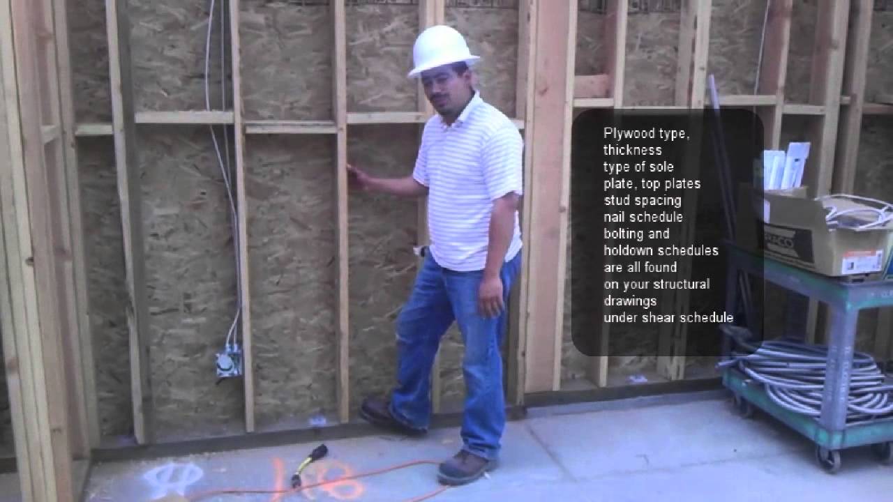
This course has been approved by aia 1 hsw lu and icc 0 10 ceu.
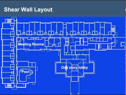
Shear wall panels explained.

What Is Shear Wall Why And Where It Is Provided Civil Snapshot

Site Built Shearwall Designer
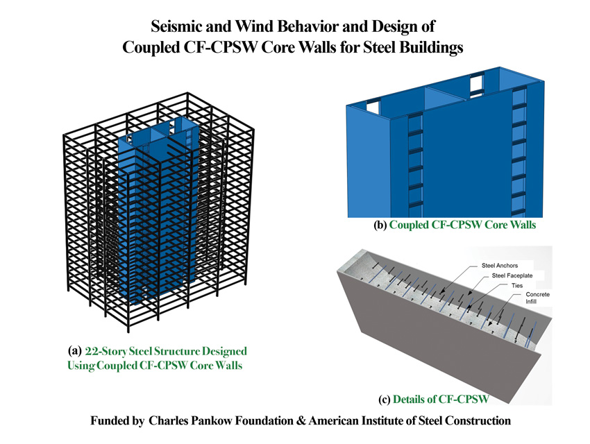
Ce Center Introducing The Steel Plate Composite Core
What Is The Basic Difference Between Shear Wall And Retaining Wall Quora

Structural Design Of Lateral Resistance To Wind And Earthquake For The Home Inspector Internachi

Narrow Shear Wall Solution Jlc Online

Stiffwall Shear Wall System Light Steel Framing The Steel Network Inc Tsn Light Steel Framing Studs Track Joists Connectors

What Is Shear Wall Its Types And Location In Buildings

Strength And Stiffness Of Cross Laminated Timber Clt Shear Walls State Of The Art Of Analytical Approaches Sciencedirect
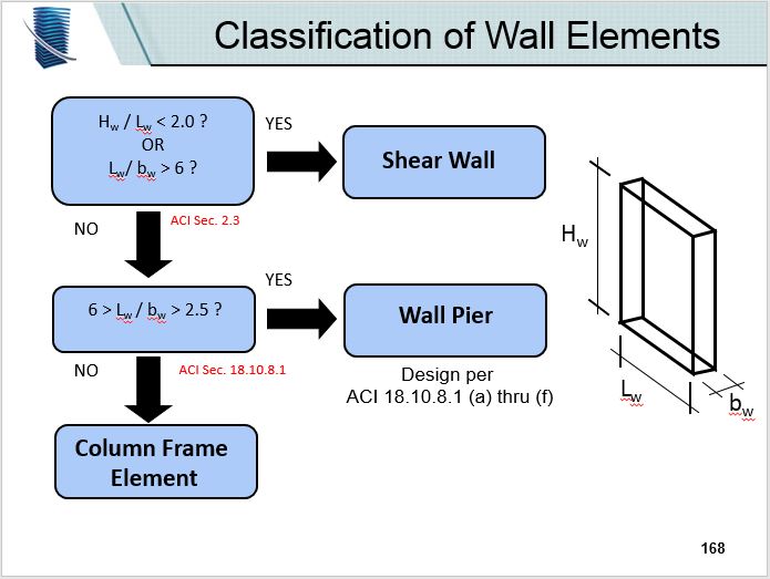
Tilt Up Walls Shear Wall Wall Pier Or Column Frame Element Se Impact Find Your Engineer
Steel Plate Shear Wall Wikipedia

Shearwalls 101 Why You Can T Have A Window There Build Blog Wall Frame Design Wooden Wall Design Wall Design
What Is The Difference Between Shear Wall And Normal Wall Quora

Experimental Study And Associated Mechanism Analysis Of Horizontal Bolted Connections Involved In A Precast Concrete Shear Wall System Sun 2019 Structural Concrete Wiley Online Library

Economical Shearwall Design Jlc Online

Horizontal Load Path For Engineered Bahareque Shear Walls Download Scientific Diagram

Building Terms Explained Shear Walls Norbord North American Products

Development Of Prefabricated Composite Energy Dissipating Slotted Shear Wall Sciencedirect
Https Encrypted Tbn0 Gstatic Com Images Q Tbn 3aand9gcslatslvkajrsgtacdx1zldcx7rjnmnk52zh31zssjbitexfjuj Usqp Cau

Des413 1 Shear Wall Design Examples Youtube

What Is Shear Wall What Does Shear Wall Mean Shear Wall Meaning Definition Explanation Youtube
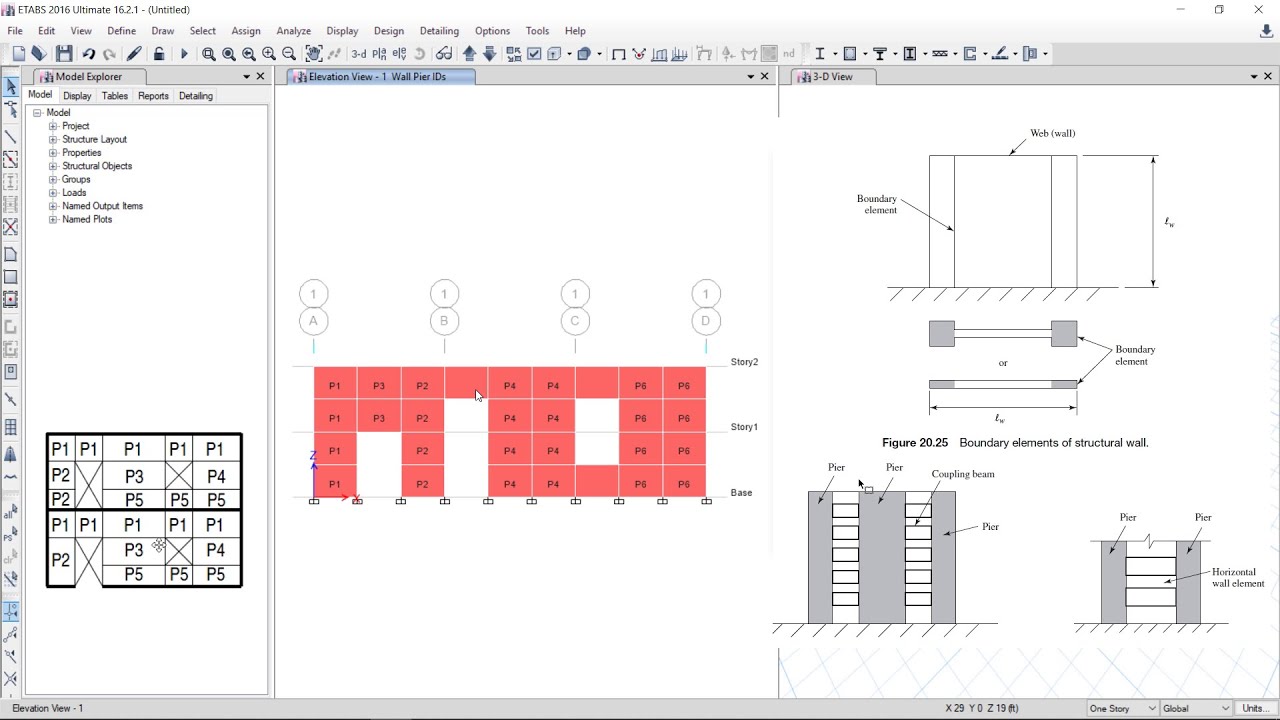
Csi Etabs 22 Shear Wall Design In Simplest Way Example 1 Youtube

Development Of An Amplified Added Stiffening And Damping System For Wood Frame Shear Walls
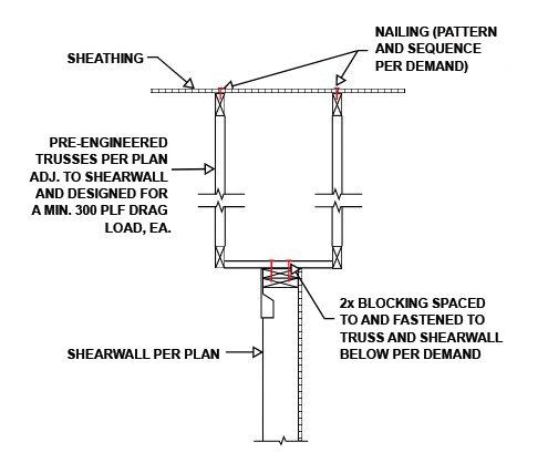
Structure Magazine Drag Trusses

Pdf A Numerical Approach For Simulating The Behaviour Of Timber Shear Walls

Lateral Loads An Overview Sciencedirect Topics
Cfs Shear Wall Design Examples And Solutions Youtube

Elastic Shear Buckling Of Sinusoidally Corrugated Steel Plate Shear Wall Sciencedirect

Pdf Estimation Of Shear Strength Of Structural Shear Walls

Hardy Frame Shear Wall System Hfxpanel House Styles Architecture Design House Design

Ce Center

Pdf Strain Distribution In Osb And Gwb In Wood Frame Shear Walls
Https Www Woodworks Org Wp Content Uploads Part 4 Shearwall Design Examples Pdf

Shear Wall Analysis Made Easy Apa The Engineered Wood Association

Awc Archives Simpson Strong Tie Structural Engineering Blog

Creativity In Structural Engineering Designing Suspended Shear Walls Structural Focus

Why Do We Have Shear Walls Inside Of A Building Interview Question 15 Youtube

Seismic Response Of Cfs Shear Walls Sheathed With Nailed Gypsum Panels Numerical Modelling Sciencedirect
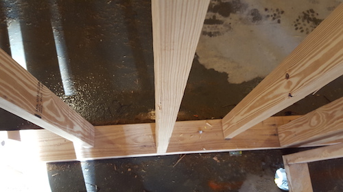
When Is Blocking Bracing Within Wood Frame Walls Required What Is Considered Adequate Bracing For Wood Wall Studs In Their Weak Axis Woodworks
Http Www Woodworks Org Wp Content Uploads Tx Wind Workshops Hour 3 Shearwalls And Diaphragms Pdf

Shear Wall Reinforcement In Detail Youtube
Applied Sciences Free Full Text Piecewise Function Hysteretic Model For Cold Formed Steel Shear Walls With Reinforced End Studs Html

Rc Shear Wall Plan Google Search Architecture Frame Concrete Building
Https Encrypted Tbn0 Gstatic Com Images Q Tbn 3aand9gctx0bjfevxrbvuz Nzsp4xw8jnqkhqtvlihwvhygx19x Pwkv4j Usqp Cau
Source : pinterest.com
